- 您现在的位置:买卖IC网 > Sheet目录39249 > LM4842LQ/NOPB (NATIONAL SEMICONDUCTOR CORP) 2 CHANNEL(S), TONE CONTROL CIRCUIT, QCC28
Application Information
ELIMINATING OUTPUT COUPLING CAPACITORS
Typical single-supply audio amplifiers that can switch be-
tween driving bridge-tied-load (BTL) speakers and single-
ended (SE) headphones use a coupling capacitor on each
SE output. This capacitor blocks the half-supply voltage to
which the output amplifiers are typically biased and couples
the audio signal to the headphones. The signal return to
circuit ground is through the headphone jack’s sleeve.
The LM4842 eliminates these coupling capacitors. Amplifi-
erA+ (pin 28 on MT/MH) is internally configured to apply
V
DD/2 to a stereo headphone jack’s sleeve. This voltage
matches the quiescent voltage present on the AmpAout- and
AmpBout- outputs that drive the headphones. The head-
phones operate in a manner very similar to a bridge-tied-
load (BTL). The same DC voltage is applied to both head-
phone speaker terminals. This results in no net DC current
flow through the speaker. AC current flows through a head-
phone speaker as an audio signal’s output amplitude in-
creases on the speaker’s terminal.
When operating as a headphone amplifier, the headphone
jack sleeve is not connected to circuit ground. Using the
headphone output jack as a line-level output will place the
LM4842’s one-half supply voltage on a plug’s sleeve con-
nection. Driving a portable notebook computer or audio-
visual display equipment is possible. This presents no diffi-
culty when the external equipment uses capacitively coupled
inputs. For the very small minority of equipment that is
DC-coupled, the LM4842 monitors the current supplied by
the amplifier that drives the headphone jack’s sleeve. If this
current exceeds 500mA
PK, the amplifier is shutdown, pro-
tecting the LM4842 and the external equipment. For more
information, see the section titled "Single-Ended Output
Power Performance and Measurement Considerations".
OUTPUT TRANSIENT ("POPS AND CLICKS")
ELIMINATED
The LM4842 contains advanced circuitry that eliminates out-
put transients ("pop and click"). This circuitry prevents all
traces of transients when the supply voltage is first applied,
when the part resumes operation after shutdown, or when
switching between BTL speakers and SE headphones. Two
circuits combine to eliminate pop and click. One circuit
mutes the output when switching between speaker loads.
Another circuit monitors the input signal. It maintains the
muted condition until there is sufficient input signal magni-
tude (>22mV
RMS, typ) to mask any remaining transient that
may occur. (See Turn On Characteristics).
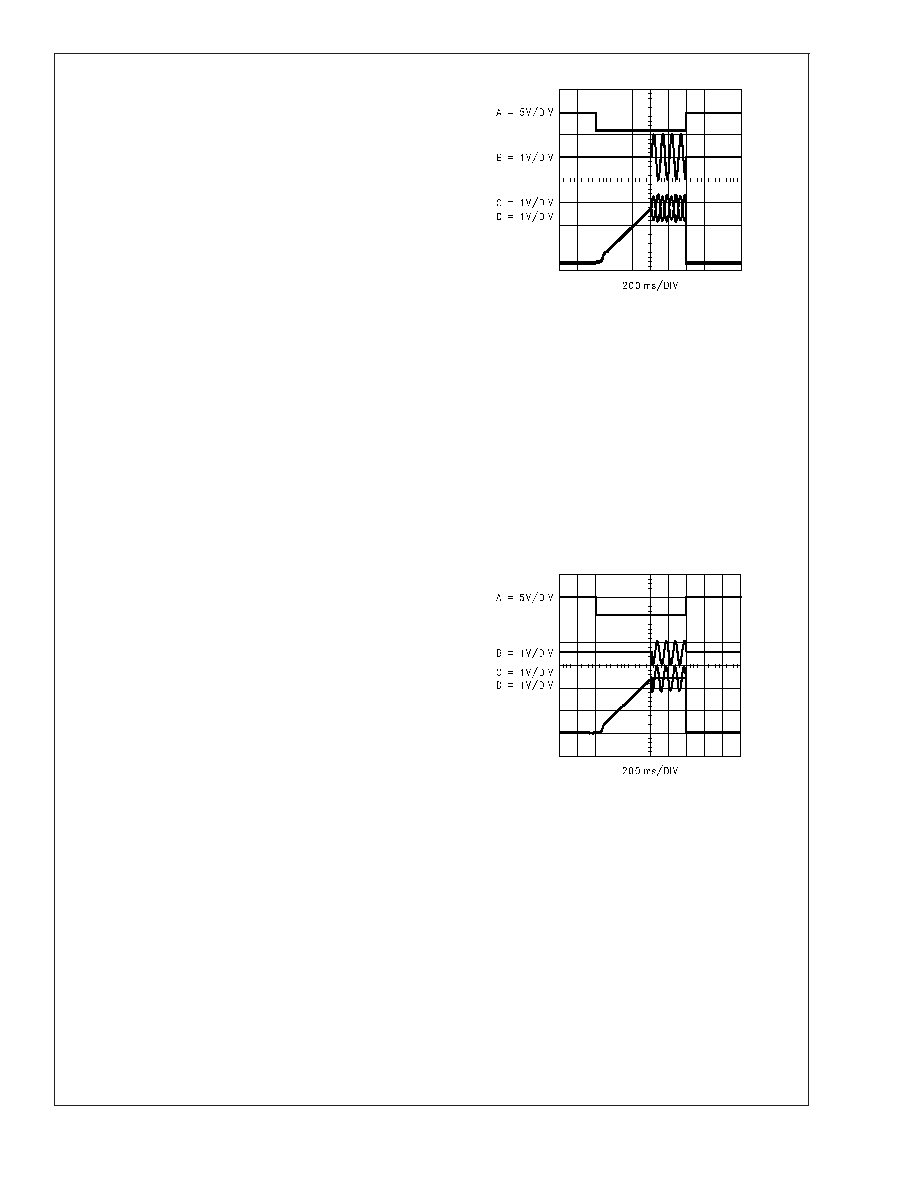
Figure 3 shows the LM4842’s lack of transients in the differ-
ential signal (Trace B) across a BTL 8
load. The LM4842’s
active-high SHUTDOWN pin is driven by the logic signal
shown in Trace A. Trace C is the VOUT- output signal and
trace D is the VOUT+ output signal. The shutdown signal
frequency is 1Hz with a 50% duty cycle. Figure 4 is gener-
ated with the same conditions except that the output drives a
32
single-ended (SE) load. Again, no trace of output tran-
sients on Trace B can be observed.
EXPOSED-DAP PACKAGE PCB MOUNTING
CONSIDERATIONS
The LM4842’s exposed-DAP (die attach paddle) package
(MH,LQ) provides a low thermal resistance between the die
and the PCB to which the part is mounted and soldered. This
allows rapid heat transfer from the die to the surrounding
PCB copper traces, ground plane and, finally, surrounding
air. The result is a low voltage audio power amplifier that
produces 2.1W at
≤ 1% THD with a 4 load. This high power
is achieved through careful consideration of necessary ther-
20028198
FIGURE 3. Differential output signal (Trace B) is devoid
of transients. The SHUTDOWN pin is driven by a
shutdown signal (Trace A). The inverting output (Trace
C) and the non-inverting output (Trace D) are applied
across an 8
BTL load.
20028199
FIGURE 4. Single-ended output signal (Trace B) is
devoid of transients. The SHUTDOWN pin is driven by
a shutdown signal (Trace A). The inverting output
(Trace C) and the V
BYPASS output (Trace D) are applied
across a 32
BTL load.
LM4842
www.national.com
17
发布紧急采购,3分钟左右您将得到回复。
相关PDF资料
LM4849MH/NOPB
2 CHANNEL(S), VOLUME CONTROL CIRCUIT, PDSO28
LM4867MTE/NOPB
3 W, 2 CHANNEL, AUDIO AMPLIFIER, PDSO20
LM4867MT/NOPB
1.5 W, 2 CHANNEL, AUDIO AMPLIFIER, PDSO20
LM4867LQ/NOPB
3 W, 2 CHANNEL, AUDIO AMPLIFIER, PQCC24
LM4867LQX/NOPB
3 W, 2 CHANNEL, AUDIO AMPLIFIER, PQCC24
LM4882MM/NOPB
0.48 W, 1 CHANNEL, AUDIO AMPLIFIER, PDSO8
LM4882M/NOPB
0.48 W, 1 CHANNEL, AUDIO AMPLIFIER, PDSO8
LM556ICN
DUAL PULSE; RECTANGULAR, TIMER, PDIP14
相关代理商/技术参数
LM4842MH
制造商:NSC 制造商全称:National Semiconductor 功能描述:Stereo 2W Amplifiers with DC Volume Control Transient Free Outputs, and Cap-less Headphone Drive
LM4842MH/NOPB
功能描述:IC AMP AUDIO PWR 2.2W AB 28TSSOP RoHS:是 类别:集成电路 (IC) >> 线性 - 音頻放大器 系列:Boomer® 产品培训模块:Lead (SnPb) Finish for COTS
Obsolescence Mitigation Program 标准包装:2,500 系列:DirectDrive® 类型:H 类 输出类型:耳机,2-通道(立体声) 在某负载时最大输出功率 x 通道数量:35mW x 2 @ 16 欧姆 电源电压:1.62 V ~ 1.98 V 特点:I²C,麦克风,静音,短路保护,音量控制 安装类型:表面贴装 供应商设备封装:25-WLP(2.09x2.09) 封装/外壳:25-WFBGA,WLCSP 包装:带卷 (TR)
LM4842MT
制造商:NSC 制造商全称:National Semiconductor 功能描述:Stereo 2W Amplifiers with DC Volume Control Transient Free Outputs, and Cap-less Headphone Drive
LM4842MT/NOPB
功能描述:IC AMP AUDIO PWR 2.2W AB 28TSSOP RoHS:是 类别:集成电路 (IC) >> 线性 - 音頻放大器 系列:Boomer® 产品培训模块:Lead (SnPb) Finish for COTS
Obsolescence Mitigation Program 标准包装:2,500 系列:DirectDrive® 类型:H 类 输出类型:耳机,2-通道(立体声) 在某负载时最大输出功率 x 通道数量:35mW x 2 @ 16 欧姆 电源电压:1.62 V ~ 1.98 V 特点:I²C,麦克风,静音,短路保护,音量控制 安装类型:表面贴装 供应商设备封装:25-WLP(2.09x2.09) 封装/外壳:25-WFBGA,WLCSP 包装:带卷 (TR)
LM4843
制造商:NSC 制造商全称:National Semiconductor 功能描述:Stereo 2W Audio Power Amplifiers with DC Volume Control
LM4843MH
制造商:NSC 制造商全称:National Semiconductor 功能描述:Stereo 2W Audio Power Amplifiers with DC Volume Control
LM4843MHX
功能描述:IC AMP AUDIO PWR 2.2W AB 20TSSOP RoHS:是 类别:集成电路 (IC) >> 线性 - 音頻放大器 系列:Boomer® 产品培训模块:Lead (SnPb) Finish for COTS
Obsolescence Mitigation Program 标准包装:2,500 系列:DirectDrive® 类型:H 类 输出类型:耳机,2-通道(立体声) 在某负载时最大输出功率 x 通道数量:35mW x 2 @ 16 欧姆 电源电压:1.62 V ~ 1.98 V 特点:I²C,麦克风,静音,短路保护,音量控制 安装类型:表面贴装 供应商设备封装:25-WLP(2.09x2.09) 封装/外壳:25-WFBGA,WLCSP 包装:带卷 (TR)
LM4844
制造商:NSC 制造商全称:National Semiconductor 功能描述:Stereo 1.2W Audio Sub-system with 3D Enhancement